With one major objective being the establishment, cultivation, and/or harvesting of row crops, it would need to know where these rows need to be for planting, or where the existing ones are for cultivation or harvesting.
To plant, it would need to know;
The precise lat long of the beginning and end of each straight row, or;
The area to plot in, the necessary turn-around area, and row widths for the crop to plant.
For non-straight rows, it would need to know enough intermediate points or a formula that described the shape of the row.
To cultivate or harvest, it would need to know the same information as above (if strictly GPS-based), or at least the corners of the area with rows, with a reliance on vision-based row interpretation. If it had planted the rows, that saved information would be available to be utilized.
And then there is the safe route planning for ingress to the field (when equipped) and egress from the field when done for preparation for the next task.
Route planning and monitoring safety can cover the areas of (and yes, credits to Isaac Asimov for the general themes);
Do no harm to people, pets, or livestock: This would most certainly require vision and/or other sensing device for collision avoidance
Do no harm to non-fixed objects: Such as row covers, temporary fences, vehicles, farm implements, etc.
Avoid collisions with fixed objects: Trees, telephone poles, fences, buildings, various hardware like wellheads.
Avoid traversing areas where known hazards/issues have been identified, e.g., a low lying area where it has been stuck before after x inches of rain, nearby roadways or trails (related to 2), or any area identified as off-limits.
It must obey orders given it by authorized human beings except where such orders would conflict with 1, 2, or 3.
Plan routes favoring preferred traversal corridors, such as on-farm ‘roads’ and paths created for it. For example, the most efficient route that would cut across rows of soybean would achieve a lower score than one that skirted the edge of the field. However, if such a route could go through such a field in the direction of the rows without harming crops, that would be a viable one.
All traversals and field work can be monitored for energy consumption by conditions and configuration to continuously improve the route planning energy estimates.
Hence, route planning needs find the most efficient route that avoids fixed objects and hazards, while route monitoring needs to ensure all the above is avoided, with rerouting in the event of a collision detection risk.
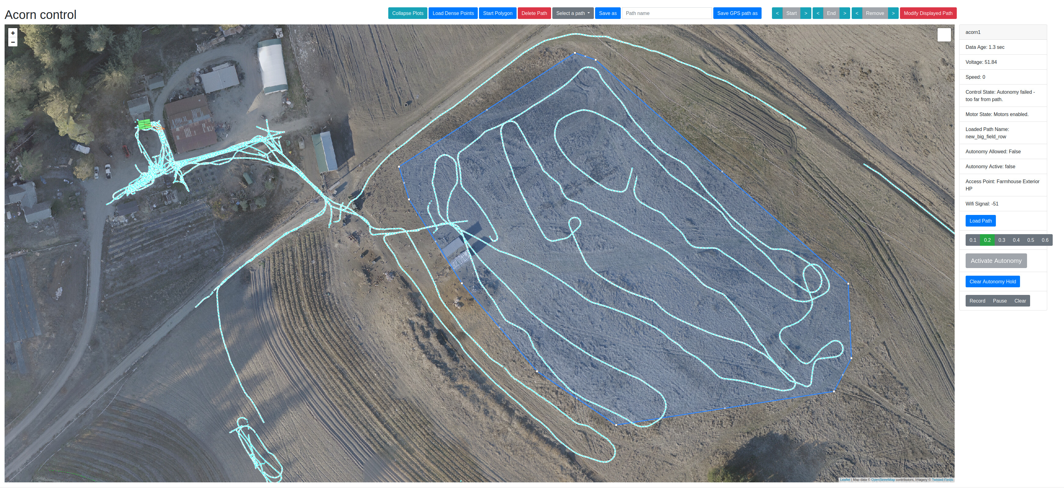
Currently we manually record GPS paths under human remote control. The paths are high density and cover any twists and turns needed. We save those paths in the database and you can use the web interface to select a path, and preview or edit them. Then you can load the selected path on to acorn. If Acorn is within a meter of the path it will start driving along it.
We will expand this soon with a server side composer that combines multiple paths and sends that to Acorn. As we get to whole-farm operation we will build an automatic planner to compose path segments together.
At some point we intend to add a 360 degree vision system to Acorn similar to the camera system on my Rover robot:
With the full camera system we will be able to do automatic row following, and we will also be able to do vision guided driving. With vision guided mapping the whole navigation system will change.
For GPS only operation I would like to add a big “stop bar” aka a large “bumper switch” on the front and rear of the machine that will activate the e-stop. Before the full four camera system we may also want to look at front and rear safety cameras, though it is hard to get provable safety from a camera system. LIDAR may be an interesting option too as prices are coming down. Provable safety from LIDAR is easier, though our biggest safety strategy is to make Acorn unlikely to hurt you.
I have a hilly and bumpy farm with slopes upto 17% grade.
Where do I find specs on Acorn hill climb capability?
Even within the current limitations, I can see using Acorn to explore a field to generate a 3d point cloud of surface topography, or find its way along contours. Once it has made a map, I could pick points to plant trees, and have Acorn go spray a paint spot at each location.
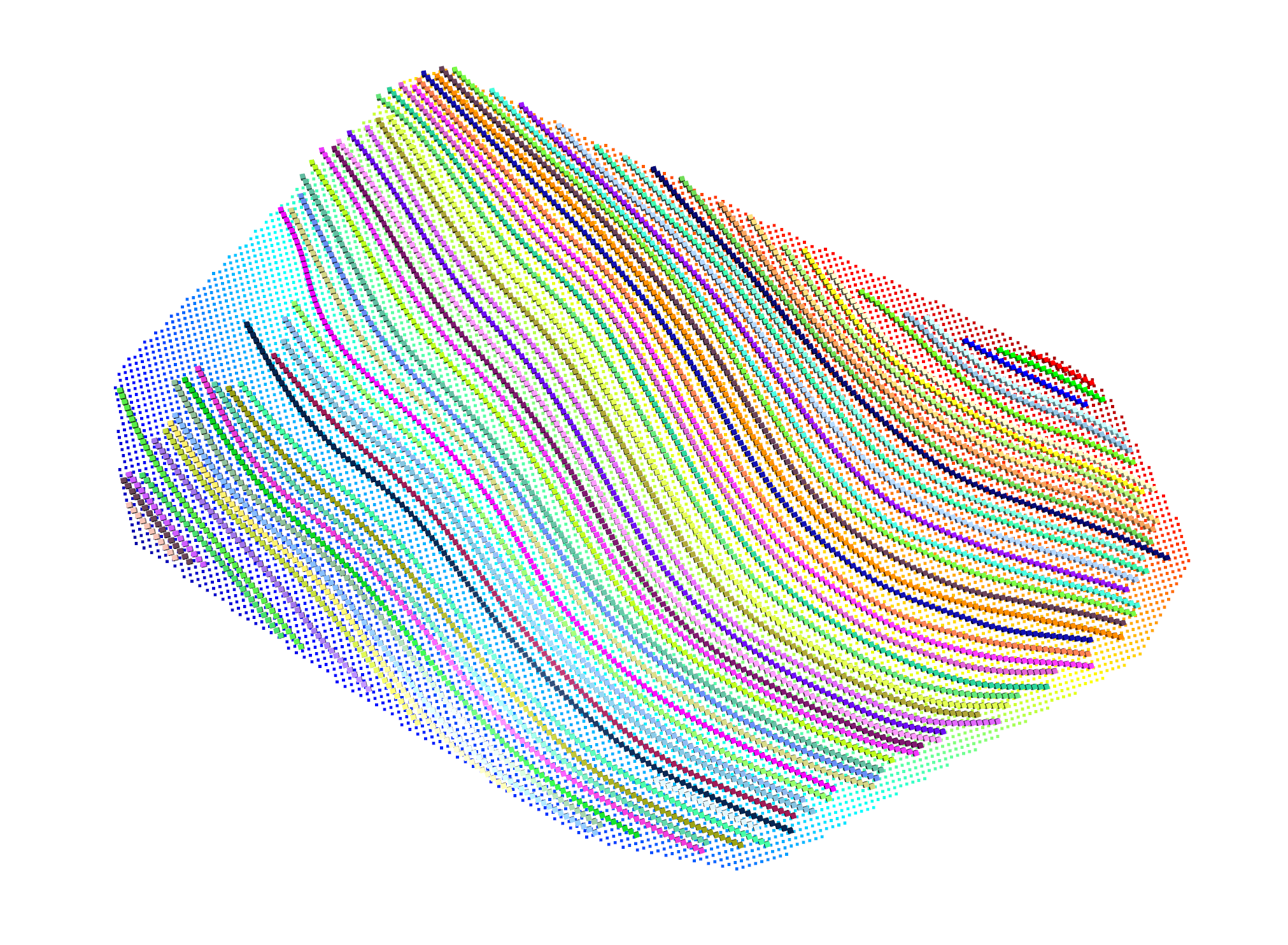
Amazingly, we are working on that right now! We also have a hilly farm and I used the precision GPS to record the general topography, then wrote code to interpolate the measurements in to a continuous surface and then calculate perfectly level rows. We have another project using raspberry pi and RTK GPS to calculate locations to plant trees on a regular grid. Haven’t hooked up a spray can to Acorn yet but that’s possible. My code for all this is not yet checked in to github but it will be.
Regarding slopes, our target was 30% grade, but most of that depends on how heavy of a tool acorn would be carrying. We still need to determine what the actual specs of our vehicle is. A lot of it comes down to the motors we have (I suspect we will end up with custom motors eventually).
Finally took some screenshots of that process. FIrst I use our web UI to load gps travel history from the database, then draw a polygon over the desired area. Then I run a program which computes level rows. I am working now on moving those calculated rows back to the database to be used as tracks to follow.
Re: I suspect we will end up with custom motors eventually.
I’ve seen that several times now. An open source commodity product like a standard spec motor will be 10-100x cheaper than a custom motor. You would need a lot of volume to get more than one source for a custom motor, I would think. Cheap Off The Shelf == COTS is cheaper and faster and multi-source, especially when the engineering is amortized over some toy product, like a power-wheels kiddie car.
Split reply for contoured tracks: I found a site that generates contour plots from Google earth data. Lots of models there, since Google earth primary data is on 20’ grids or somthing large like that. I am toying with the idea of making a physical model of my field with either 3dprinting, or 2d lasercutting for a layer-cake type model.
A potential problem with level rows is the transition between them at the edges of the field.
Can you model a near constant slope path that zig zags across the field, so that the transitions at the edges are at a similar slope to the entire row?
Am I making sense?
Ah, well when I say “custom motor” I am actually referring to a hubmotor assembly. The best drive solution I have found so far is our modified Bafang wheelbarrow hubmotors pictured in detail here:
This hubmotor is a wheel hub, axle, motor, and gear reduction. The actual electric motor itself would absolutely be COTS. If we used a different COTS motor we would still need a wheel/hub, axle, and potentially some gear power transfer. A front bicycle wheel is not designed to accept power input and a rear wheel is only designed to accept power input in one direction. So we need something “custom” to make that work. At minimum would be a gear which bolts to the disc brake details interfacing with a gearmotor bolted to a custom square tube fork. And I suppose that’s not a bad idea so I will think about that. We plan to make a custom square tube fork already as our mounting needs vary from bicycles significantly.
So a “custom hubmotor” could be basically a custom axle and hub that would accept input from a COTS gearmotor. That would be no more complex than our current solution but would still require custom wheels which has been a pain. So I will think more about mounting a gearmotor on the fork. We previously used COTS forks and mounting anything to them is a pain, but that will change.
The trick with contours is that it is easy to make a contour at a specific height. It is more complex to make a countour on a surface with varying slope which is level and is also no closer than 48" from the previous one. I tried a few approaches but the simplest was just to pick a contour and then check its distance to the previous one and slowly move down until a good one is found, and repeat.
You can see some recommended ways of finding them manually here:
A good example of zig-zag path I mean would be to consider a wheel chair ramp that replaces the entire front steps of the Lincoln memorial, or Rocky’s steps at the front of the Philadelphi art museum. There is a level turnaround at each end, and the path slope is gentle from left to right and right to left.
The manual contour method with an A-frame with level or hanging string is interesting. I’d try to add a magnetic damper to the hanging rod. The method of using a koolaid in a clear hula hoop to get a 1 piece water level is neat too.
Ah I understand what you mean about zig-zag now. If space was not at a premium that could be nice, but I think it would have less density than parallel rows. However those extra spaces could have flowers for pollinators which can be lovely.
Simplest answer is yes. Acorn can among other things accept a raw list of GPS coordinates and follow them, though our more advanced path following spec includes desired control system parameters. But if there’s existing data formats we can consume them as needed if we write a simple importer.
Hi Sam and Taylor, that is very interesting, thank you both. I am dealing with building our robot my son is dealing with the electronic side, way above my pay grade. Where my son is struggling with is the brushless wheel motors, with the chip board he is using, if that is the right word. Does your chip board accommodate brushless motors? Taylor I really appreciate you openness and I am trying to get my son to join in the chat forum, which I think would speed things up. Happy New Year to you all