Motor and controller selections

I’ve been trying to find a zero-rake fork. That is, a fork where the wheel axel is in line with the steering rotational axis. Such a fork is important so that the robot behaves the same going forward or backward. Have you been able to find such a fork?

2 Likes

Welcome @jepeloa and @JohnETanner!

That’s a great article on e-bike wheels with ROS, thank you!

We are currently using this geared wheelbarrow motor which has a 30:1 gear reduction inside. I designed a modification that allows them to be fitted with regular mountain bike wheels (photos up thread).

I wanted to use some other geared hub motors before:

But I eventually realized the higher gear ratio of the wheelbarrow motor meant better electrical efficiency and thus lower power use.

See:
https://ebikes.ca/tools/simulator.html?motor=MG311_WB&cont=cust_60_70_0.03_A&hp=0


and:
https://ebikes.ca/tools/simulator.html?motor=GMAC10T&cont=cust_60_70_0.03_A&hp=0

See that at 5kph the GMAC hub motor is 38% efficient, while the wheelbarrow hub motor is 50% efficient.

We also get a lot more torque from the wheelbarrow motor which I suppose helps with efficiency more. Right now Acorn draws 20 watts while driving on level ground at walking pace!

Okay for the fork @JohnETanner:

It’s a good question. We’re not using zero rake forks. However we will probably end up making custom forks as adapting a normal fork ends up costing money too. Right now the forks have a rake, and we orient all the forks so the rake is facing inward. That means whatever slight error is caused by the rake will be symmetric with respect to the direction of travel. It also means our homing sensors can be the same on all four corners. I think with a little care, math errors due to rake could be incorporated in to the steering algorithm, though right now they are ignored.

Oh also @jepeloa since you shared your code it reminded me. I haven’t documented our code yet but here are the functions for exposing our motor control over a network socket on the pi. We connect to that socket with our main control program to drive the system.

We’re interested in using the geared wheelbarrow motor which has a 30:1 gear reduction inside. The ebikes site has limited specifications on it and I can’t find anything on the Bafang (the manufacturer’s) website. Do you have a datasheet or detailed specifications on that wheelbarrow motor that you can share? One item of specific interest is the operating voltage that we’re guessing is 36V from your posted simulations but we’re trying to get confirmation.

1 Like

I don’t have detailed specifications. However brushless motors generally can accept a wide input voltage, as they ultimately care most about the drive current (which should be regulated). I’ve been advised to limit drive current to 40A by the ebike folks. We’re driving the motors at a max of 50v.

Also I used Acorn to carry a heavy roller over some crops in a field and it did great, so the motors have good torque!

The specs are here, but with a different (unspecified) gear ratio.

https://bafang-e.com/oem-area/components/component/motor/fm-g311250vd/

50V exceeds the rated voltage, however what this means, in practical terms, is that you are electrically able to exceed the design (rated) top speed for the motor. Whether or not the actual hardware will have any issues is a totally separate question. Given that you are generally lightly loading these motors, it’s likely not an issue, but it’s experimental and not design intent.

The real voltage limit is going to be in the connectors, insulation for a low voltage motor rarely has less than hundreds of operating volts of capacity for extremely conservative safe operation. Typically, assuming Bafang quality tests their products, this will be Hipot tested for 1500VAC+. The motor may not see a short at that kind of voltage in a short test, but if you run it at say, 300VDC switched, you may start boring microscopic holes in the wire insulation. Certainly you will likely cause failure at the connector.

Again though, you are switching 50V you aren’t actually operating at a full 50V unless you operate at the 50V top speed. So insulation and your controller’s ability to switch the higher than design voltage are your limiters, not the motor winding design.

I’ve designed many 48VDC switched motors that can be switched by 1000VDC safely, you just can’t spin them fast enough to actually utilize the high voltage. As such, the high voltage is just beating up your FETS and requiring higher switching frequencies to compensate for the low resistance and inductance it’s switching against.

Conclusion, if it’s been fine you’re fine :wink: In a next version though I’d like to consider a lower cost motor with a 3D printed reduction rather than using this hub motor. The efficiency for these hub motors is very poor, we should be targeting moderately loaded efficiencies around 80% and cruising >70%, at this price range.

2 Likes

Given my calculations results here, I’m going to think through designing around a 180Nm target with a top speed at 42VDC switched nominal of about 60RPM, which is ~5MPH (8km/h).

This achieves your mass/slope targets even with traction concerns on uneven ground, but you can still chase it down.

I uh… I have a small concern about it shoving a bit hard if it hits a person while driving, however there should be some considerations for this, be it a bumper with an indicator switch, forward camera, or feedback loop recognizing a dramatic speed change without a corresponding tilt from a slope or uneven ground.

EDIT: This would not produce full torque at top speed, rather a 250W limit is likely a good rule of thumb. That puts this at a base speed of 1.25MPH up the maximum slope at full weight, at 42VDC switched on the motor leads.

2 Likes

Thanks for the great analysis! It looks like your link is for a different part. Here’s the part number off of one of our motors.


Interesting, the 230D is not listed on Bafang’s site. According to your link for the wheelbarrow hub motor, the supplier there says it’s the same motor as the one I linked. The electrical specs should be the same, the ratio increase will change the torque/speed specs and may reduce the overall efficiency as well vs the linked version.

@Taylor does the OnShape library include the interface dimensions from the Bafang motor where you replaced the case? I’m wondering if you can share those in any way.

1 Like

Been doing research and even contacting some chinese suppliers, there is no existing option that will check all the boxes without going to >750W and at a higher price. Since Bafang only sells through distributors and they are already almost the peak of performance out of China/Taiwan, it definitely seems to me that the only way to move forward is to use 750W+ motors (not actually utilizing the high speed range, so always operating at low speed) OR to make a custom gear reduction.

In terms of the gear reduction, a 3D printed strain wave gear could be a solid option, though I’ve never designed one myself. A 3D printed or off-shelf part 2-stage planetary is another option. The issue with 3D printing the reductions is of course the efficiency. The strain wave may offer the best overall option for a printed reduction.

The main reason I think a new motor will be needed is because of supply, the wheelbarrow motor has been removed from Bafang’s manufacturing plan. The reason you used it was the higher torque rating and ultimately it isn’t even the desired level of torque for the project requirements.

In fact, I see a huge gap in the market in this level of torque in a hub motor. Most hub motors are focused on high speeds rather than high torque. I don’t know the downstream marketability of a low speed high torque hub motor, but it’s firmly in the medium robots range for torque and speed. Sadly I couldn’t find anything in that market that wouldn’t just be ridiculously expensive.

2 Likes

Triple post, BLEH, anyways…

CubeMars RI60 Motor (270W)
CubeMars RI60 Motor (270W) Alibaba listing

This is probably what I’d work from as a starting point. I’ve not worked with them directly, but I’ve encountered engineers that have vouched for the quality of their motors. I used to work for a company that directly competed on a few projects, though CubeMars has primarily competed in the Chinese/Taiwanese robots markets rather than in the USA, they have research partnerships with USA universities.

The motors are hand wound for higher copper density, which is… more expensive, but there are very few machine wound servo motors in this price range from any supplier. The price is substantially less than your current motor, but it does NOT include the gearing or faceplates that you are still utilizing.

1 Like

Very interesting thank you!

The wheelbarrow motor design gave me some ideas on how to construct a custom assembly (gear reduction and physical mounting for the wheel and fork) based off of this design. It could use any motor, and it would not necessarily need to fit inboard. Perhaps I will find some time to sketch it up. I should look through my photos or take some new ones and post pictures of the internals of this motor.

But for now here is the onshape link to the wheel adaptors:
https://cad.onshape.com/documents/96f5b83bdb2e3e2dbf393685/w/6b25ea979f92da945aaf37bc/e/53e36a73bf4261c61301524b

I do have some experience with planetary gearbox design.

As much as I like 3D printed plastic gears, I think they need to be metal for this application. But I would hope a 3D printed metal pinion (only costs about $30 from shapeways) and a waterjet cut ring gear might be enough reduction.

For now these wheelbarrow motors do the trick. Bafang has said they will entertain requests for customization if we’re willing to buy 500 units. However that’s approximately $100,000 in motors so if we’re going to spend that much a fully custom solution might be best. And of course we do not yet have need for 500 motors!

2 Likes

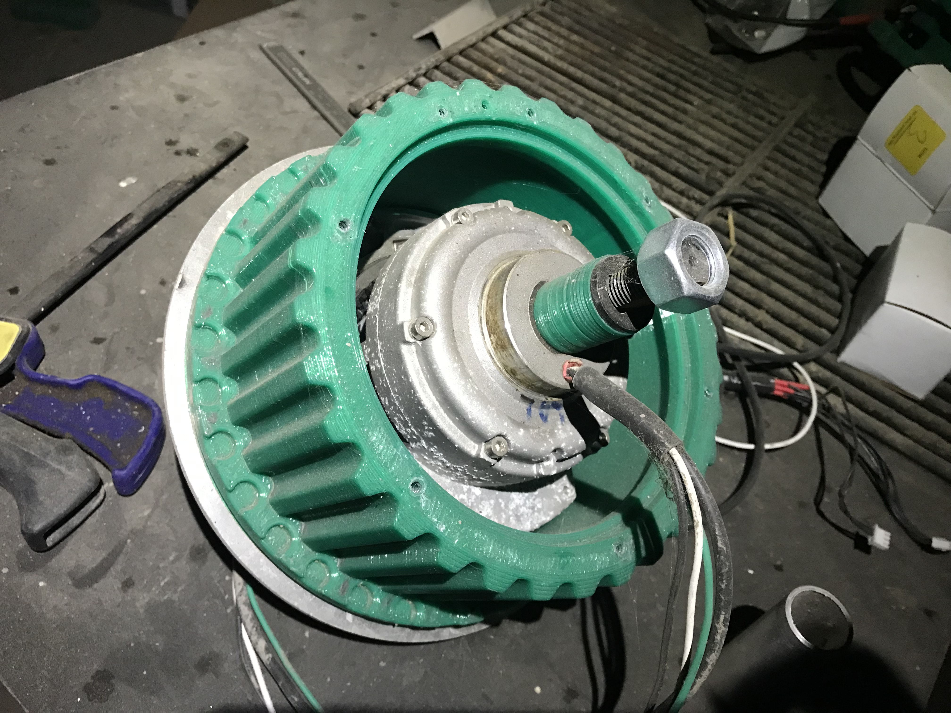
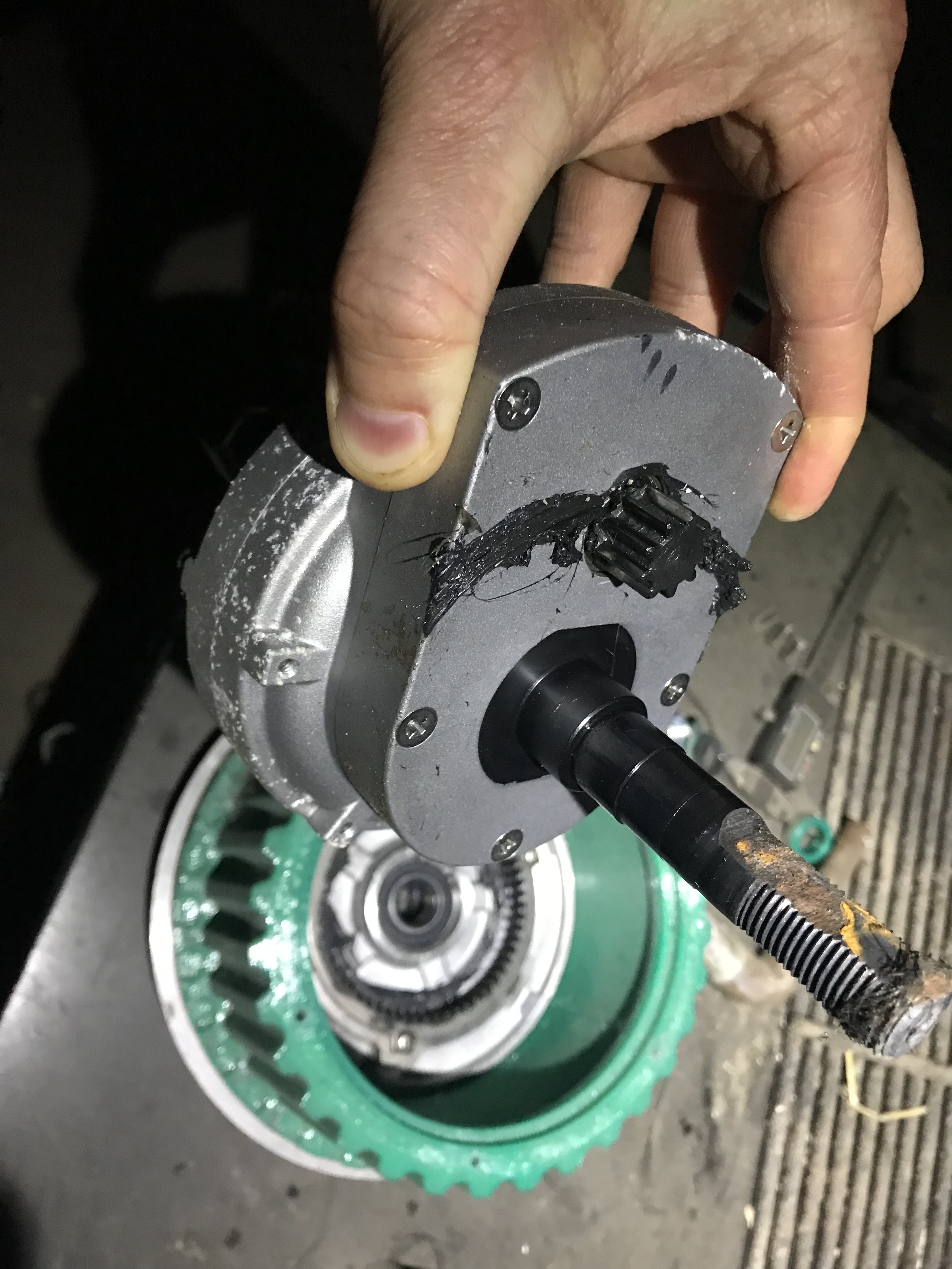
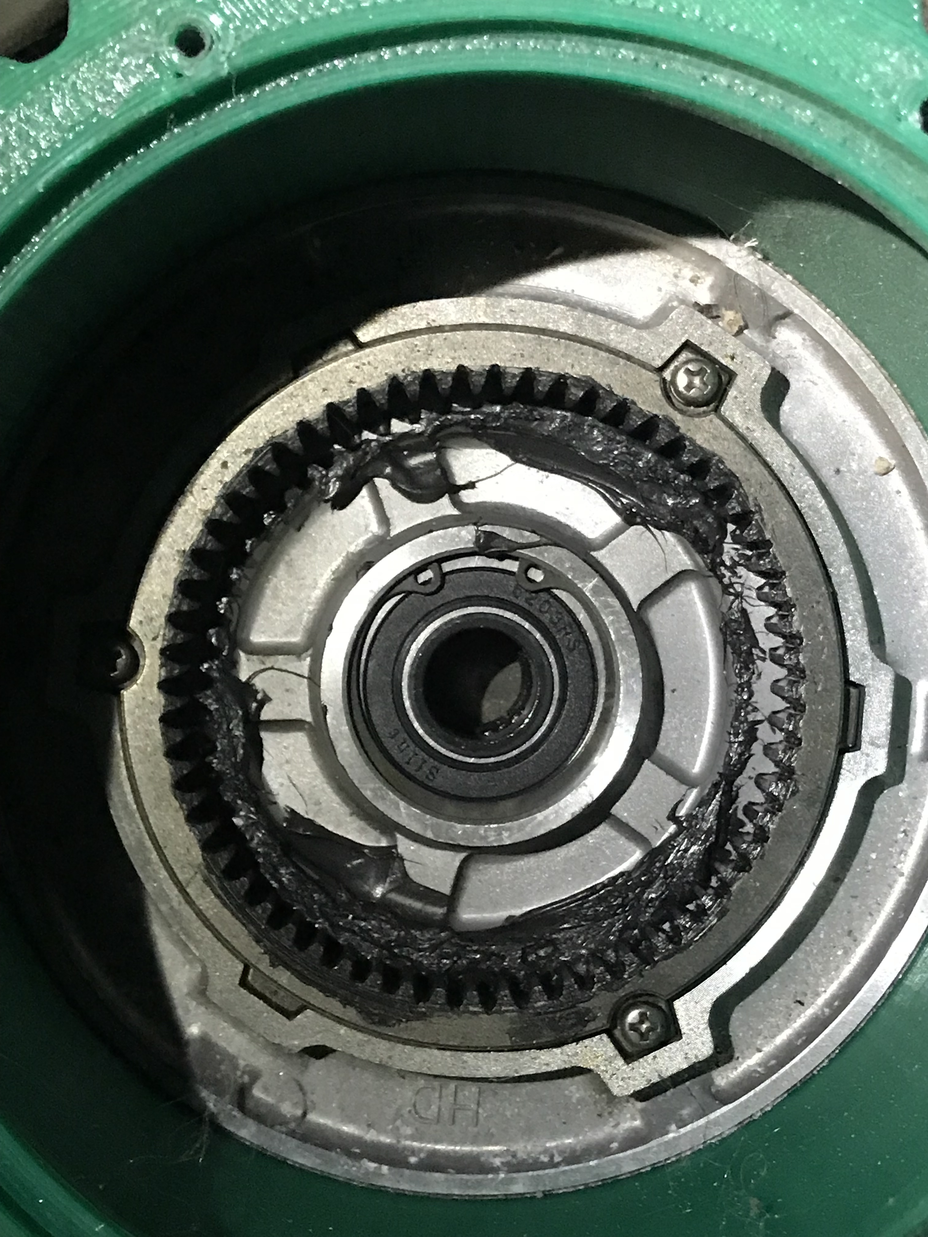
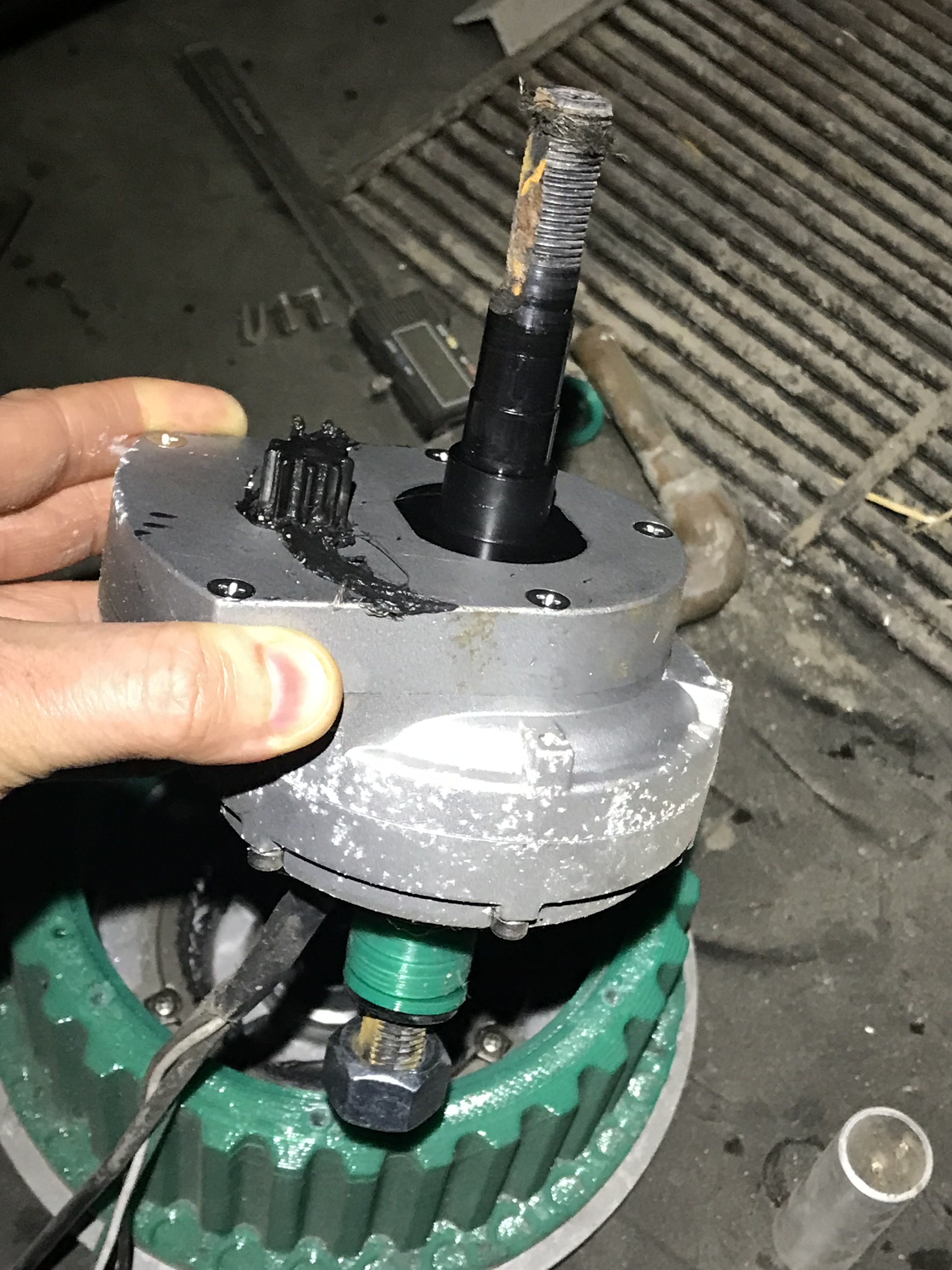
Some quick photos. Looks like two stage reduction. I want to pop that cover off and see what the internal gear is. Note that the shaft does not go through the motor. The motor housing is structural. I’ll have to share more internal photos when I have a chance.

1 Like

Yeah, it looks like they have an epicyclic + a spur or helical offset reduction. That would make sense, the epicyclic/planetary is probably standard and the offset reduction may be added just to get that higher reduction for the wheelbarrow?

1 Like

Ah yes I suppose the output is a one planet planetary huh. As far as what’s standard, it’s hard to say. But I’d love it if the other part number you found was the same and was designed to mount a wheel! I’ll have to email them and ask.

Hi Twisted Fields,

I’m attempting to use the same motor (the Bafang 30:1 geared hub motor discussed above) with the 56V V3.6 ODrive controller as you all, but I can’t get it to work! Every time I calibrate the motor, I receive an ERROR_ENCODER_ILLEGAL_HALL_STATE. Is this an issue you’ve experienced at all? I’ve checked the outputs from the hall sensors and they all seem to be reading correctly, alternating between ~0 V and ~3 V, with no points where either all three are high or all three are low. And if you’ve seen this, how did you solve it - what parameters do you use in the controller? Any help much appreciated!

1 Like

Sorry for the delay! The time that I have seen that has been when I hooked up the encoder to the wrong port. Are you using the M0 encoder port for Motor 0 and M1 port for Motor 1? If you’re still stuck DM me and I can try to help. The odrive discord channel is great too.

Update on brakes:

I’ve added a safe braking system to Acorn. Normally closed relays short the motor leads together any time the motors are not enabled. Works on power failure, e-stop, or motor fault. It’s a nice system and stops the problem of potential catastrophic runaway on a hill. Now we can operate autonomously on hills! More details incoming but I wanted to share this little tidbit.

Also that system does not completely immobilize the vehicle, just solves the risk of runaway (the unpowered motors have next to zero rolling resistance). We might implement a “parking brake” where it turns the wheels inward (opposing angles) to make a zero power complete stop on a hill.

1 Like

Re: Hub motor discussion:

A front bicycle wheel is not designed to accept power input and a rear wheel is only designed to accept power input in one direction.

I think fixed gear hub (vs single speed gear hub with freewheel) will accept power input in both directions. Take a look at this discussion: singlespeed hub
and this this example 26" mountain bike wheel

Gear and motor and brake: Have you considered a worm drive?
All your gearing in one step.
No need for additional brakes, since they usually can’t be backdriven, the wheel is locked
Some example numbers: Did I get them right? Larger wheels = lower ratios than I’ used to.
3000rpm motor, 26"dia wheel is ~72" circumference = 6’ per rev
10mph ~= 15f/s x 60s/m = 900 f/m x 1rev/6ft = 150rpm vs 3000rpm motor = 20:1 worm gear
Worm gears from 10:1 to 120:1 are available from that website for example.
The torque is probably fantastic.
The efficiency may be too low.
Need a custom worm gear box since alignment between worm and wheel is critical, and needs good lubrication supply.
A worm gear with a splined bore to fit the single speed wheel hub would have the fewest parts and the most precision, but is custom.

Motor Controllers: On brushed DC motor drivers using PWMenable for speed control, it seems like you can provide arbitrary alignment between the phases.
Either align them in pairs where one motor turns off as the other turns on, or just make sure all the rising edges are spread out.

Can brushless motor controllers do the same thing?

1 Like