This article is a text version of our latest youtube video. To watch on youtube click here:

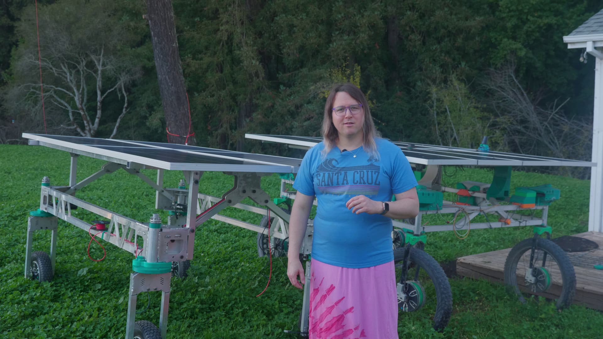
Hello everyone and welcome to Twisted Fields, our research farm in San Gregorio California. We’re developing Acorn, our open source precision farming rover. We believe that robots like this can help produce healthier food for all, reduce our reliance on harmful agricultural poisons, and fight climate change through regenerative agriculture.
in our last article, we shared an update on several developments we had completed on the robot early last year and announced our new funding platform for supporting our work.
In this article, I will share several more exciting developments as we get closer to a stable kit design suitable for shipping to early adopters. We’ve designed new electronics which will lower the cost of our system, built out a basic metal shop including a large format CNC plasma cutter for quickly fabricating parts for our robots, and perhaps most exciting - we’ve used this metal shop to build the first prototype of our new vehicle design. We’ve also started getting monthly donations from a handful of backers as we grow our new funding campaign.
If you find this project interesting, consider subscribing to our youtube channel. To be notified of every new video, click the bell icon next to the subscribe button. Finally, we’ve begun to accept tax deductible donations to support our project. Long term we hope to fund all of our engineering work through your support. These donations allow us to keep the entire project open and accessible to all. You can make a donation with just a few clicks, so if you’re interested in making a monthly or one time donation, head on over to our Open Collective page and make your contribution today. We appreciate anything you can offer. We also encourage you to sign up for free and introduce yourself right here on this forum.
Finally, it’s time to introduce you all to Daniel Theobald. Daniel came up with the idea for our solar powered farming robot and has been behind the scenes supporting this project since the beginning. We’d like to get him on here more to share his own thoughts about the project.

“Hi everyone. You know, agriculture is at the heart of every healthy community, and agriculture is hard, especially when you’re trying to grow healthy food in a sustainable way. We’re really excited about the potential of this technology to help solve that problem and sharing it with the community and seeing what all of you can do what the technology is is something that I’m really excited about. So thank you for your interest and support and I look forward to seeing you in future episodes.”
Thanks Daniel!
Now lets get on to the engineering updates.
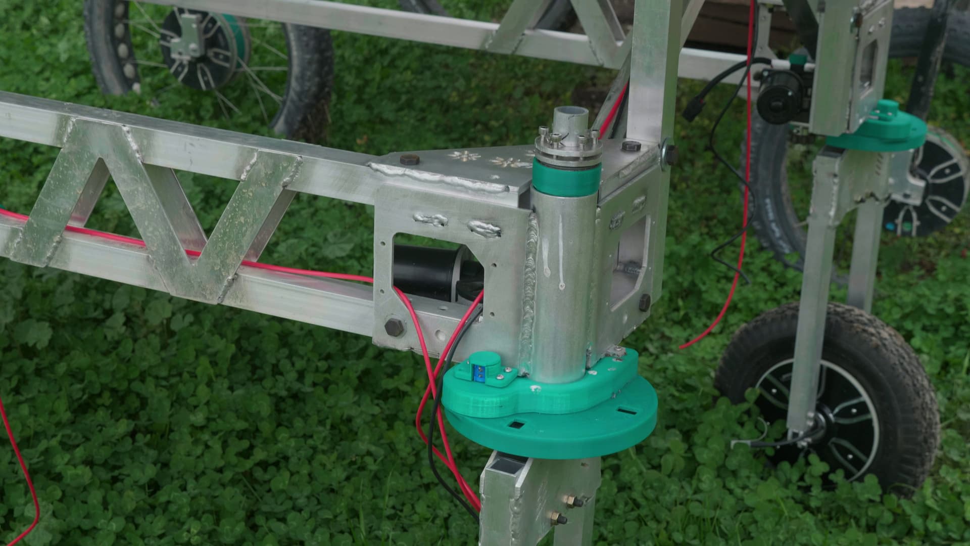
I think the most exciting thing to share is our new robot prototype under construction now. Since the start of the project we have used our original prototype vehicle as a development platform to write all of our software, test drive systems, prove out some of our fundamental concepts, and develop our electronics. But there were some issues with that design. The robot can be thought of as four identical robotic corner assemblies, linked together by a rectangular frame. The corner assembly includes a steering system and drive motor, and all of the complexity of the robot is in those corner assemblies. On the original prototype, the corner assembly is integrated in to the frame of the robot. If it has a malfunction, you have to disassemble the corner of the robot in place. On the new version, the corner assembly is modular and removable. If you have a malfunction in the field, you can remove the corner and take it to a workbench for troubleshooting, or swap in a replacement to quickly keep moving.

The new frame is more modular as well. Instead of the large single piece frame of the original, the new frame consists of side weldments bolted on to front and rear weldments. This makes it easier to change the width of the robot for different row spacings. We’re currently experimenting with 48 inch row spacing (122 cm) to allow for 30 inch beds with 18 inch walkways (76 cm beds, 43 cm walkways). This is a popular size for high density human scale organic farms, and we’re very interested in a system that works alongside people in the field. This spacing allows a person to crouch in the walkway and comfortably reach the full width of the bed. It feels like a good size for the robot, especially for rapid development of new tools. I imagine that as we develop more and more useful tools, we can let the robot do more of the farming and go to wider row widths.
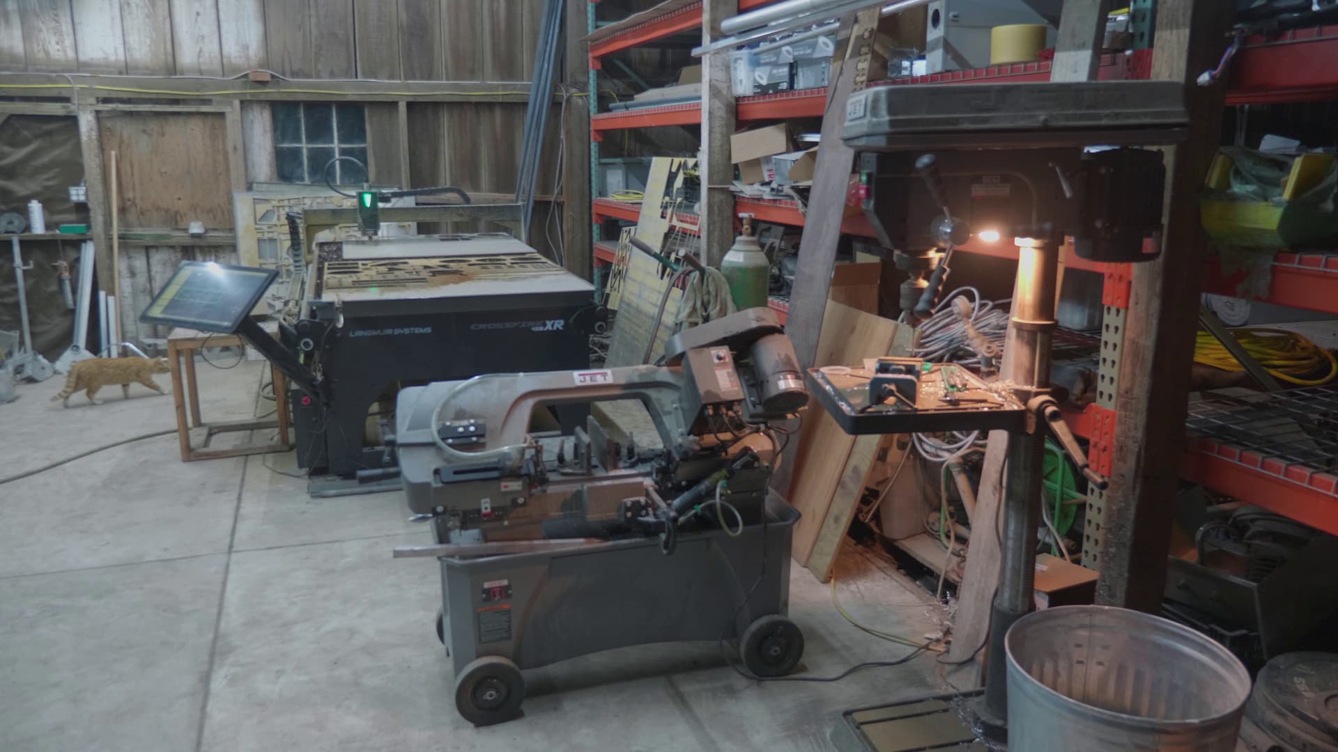
We fabricated the new frame right here in our metal shop. It doesn’t take much to build the robot yourself. Aside from basic hand tools, the only equipment required is a CNC plasma cutter, drill press, band saw for cutting tubes, and a MIG welder.

Our goal is to design a farming robot that can be built in a small shop in any city in the world. This will allow people anywhere to build these systems, sell them for profit, and build a business providing these machines to local farmers. This creates an economic engine that will drive development of newer and better designs, and a community of creators and users all over the world who can swap ideas and build on each other’s work. Of course we will sell kits to those who want them, but its important to us that anyone can build them.
In other news we’ve made significant advancements in the electronics design for our robot. This dramatically lowers the cost of our system, makes it easy for anyone put the new boards in to production, and simplifies the wiring and design of the electrical system.

In a 2021 update we showed off the motor control system of the first prototype vehicle. We relied on the ODrive motor controller plus a custom circuit board we designed to interface with our motion control system. The ODrive hardware cost $250 to control two motors, and the interface board we need adds even more cost. In conversation with ODrive we learned they are moving up market to higher end offerings, discontinuing the board we have been using, and moving some of their products to closed source software. To keep our costs low and our system flexible we decided to look for other options.
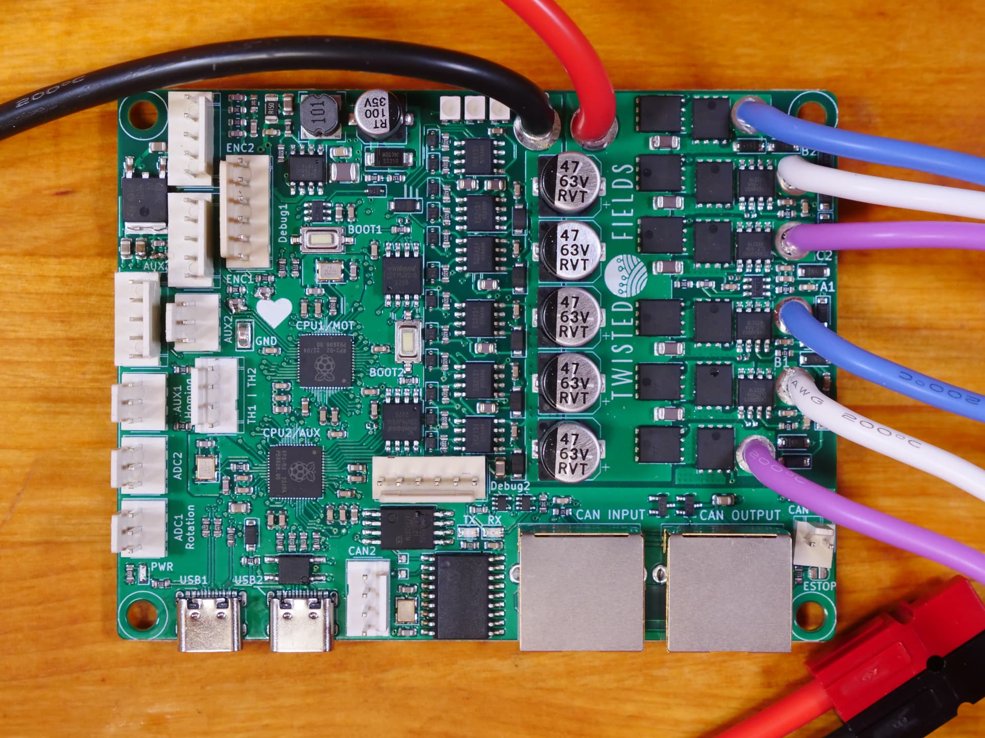
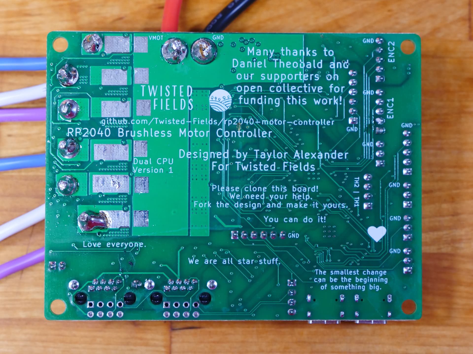
In the end, we decided to design our own custom motor controller. Our board avoids the use of specialized chips which risk supply shortages, and is designed to be fabricated using the JLCPCB assembly service. JLCPCB keeps a large library of parts in stock, which avoids the added expense of sourcing parts from vendors all over the world. By designing the board ourselves, we can add whatever interface electronics we need without requiring a second board. Our new board, which controls two motors and includes all of our custom interface electronics costs about $35 to produce. All of the design files are open source and on our github, and anyone can order them from JLCPCB with little overhead. We will maintain two versions of the board - a custom board for our robot with all the extra interface electronics we need, and a general purpose version for robotics hobbyists.
We have already confirmed the basic design works, and have since designed an updated version with all our interface electronics for the corner assembly. To get the motors spinning, we use SimpleFOC firmware designed for just such a board. Our motor controller uses the RP2040 processor, and we found a very helpful SimpleFOC developer, Richard Unger, who was kind enough to port SimpleFOC to our hardware. I think this is a testament to the power of open source. We made the hardware, found someone who had already worked on appropriate software, sent him a developer kit ready to spin a motor, and his curiosity and passion led us to success. His findings also led to some design improvements in the latest rev. Thank you so much Richard!
With all the advancements, it feels like we’re much closer to a stable kit design we can ship to early adopters. We’re working now on wiring up the new system and getting it running. From there we need to put it through long term testing and make sure there are no surprises. Then we will build a few more vehicles for advanced testing and production trials, and then hopefully we will be able to sell our first kits.
As I mentioned before, we’ve begun to receive donations to our project on our Open Collective page. These donations are tax deductible and easy to make with just a few clicks. For now these funds will be used to support the production of these video updates. As your support grows we hope to fund all of our engineering through your contributions. This will help ensure our designs can stay open and accessible to all.
If you find this all interesting don’t forget to subscribe to our youtube channel, and click the bell icon to be notified of every new update.
Finally, we would love to see you join our free community discussion forum right here at community.twistedfields.com. Sign up and introduce yourself!
That’s it for today’s update. Big thank you to our financial supporters:
Daniel Theobald, Mike Kelley, Kelly Knight, Liu Liu, Kate Sprague, Booty Tompkins, Moses Tschanz, heimi, bounding_star, Sami Anderson, Avi Brown, Guest, Cole Amick
We would like to acknowledge that Twisted Fields is located on the unceded ancestral homeland of the Ramaytush Ohlone peoples who are the original inhabitants of the San Francisco Peninsula. For more information see ramaytush.org
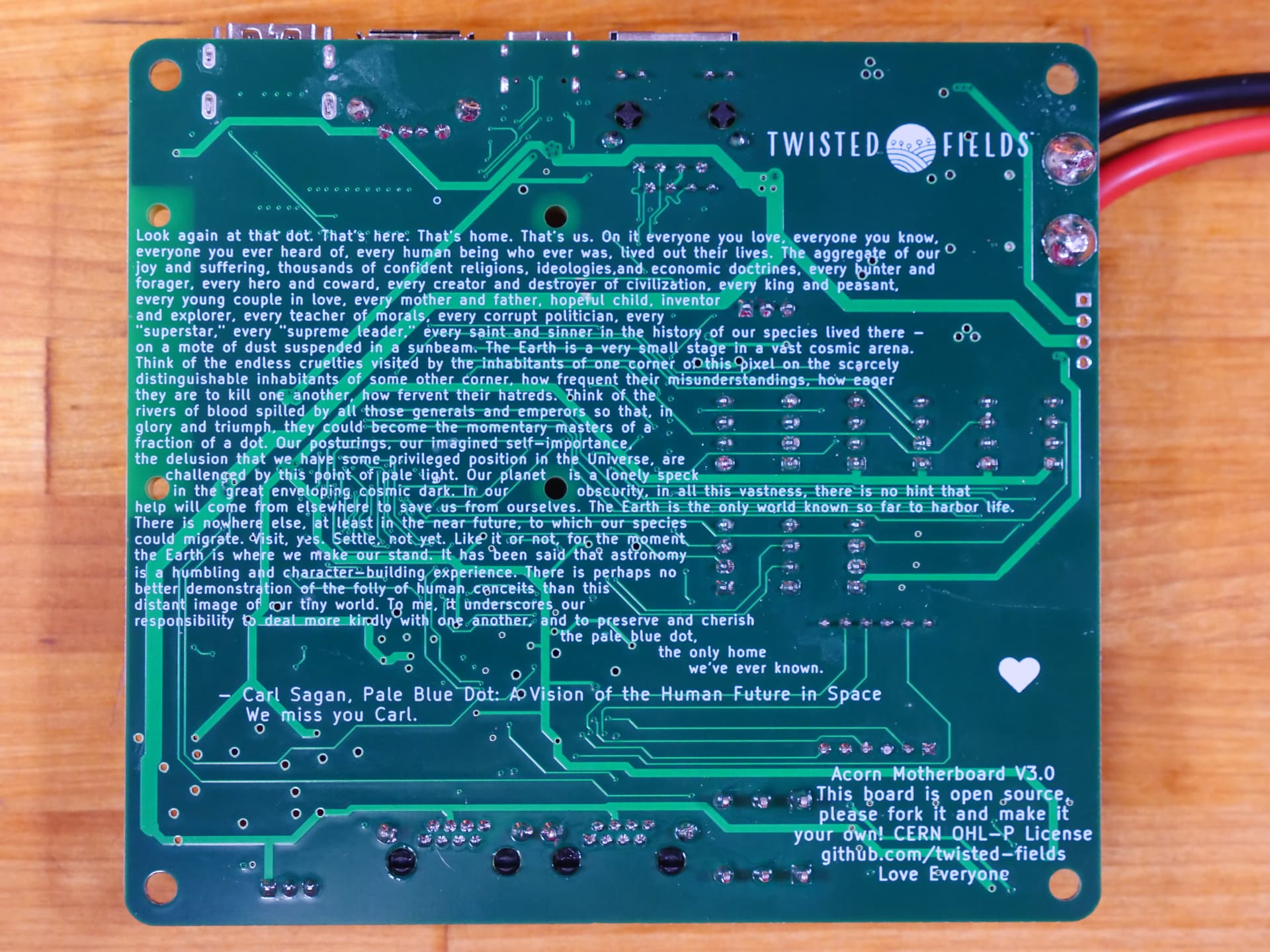
As a bonus, I wanted to share the artwork on the back of the PCBs which did not make it to the video. I always feel like there is a lot of room on the back of the PCB, and if it’s not filled it art it would be an awful waste of space.
Thanks for reading!